A Comprehensive Guide to 2:1, 4:1, 8:1, and 16:1 Multiplexers
Introduction
In the world of digital electronics, multiplexers, or MUX, are like the conductor of a symphony, seamlessly coordinating data from multiple sources to a single destination. Among the various types of MUX, the 2:1, 4:1, 8:1, and 16:1 configurations hold a significant place in modern electronic design. In this Medium post, we will delve into each of these multiplexers, exploring their operation, applications, and importance in shaping the world of digital circuits.
2:1 MUX — The Fundamental Building Block
At its core, a 2:1 MUX is the simplest form of a multiplexer. It has two data inputs (I0 and I1), one output (Y), and a single control input (S). The control input (S) acts as the selector, determining which of the two data inputs is transmitted to the output. When the control input is low (0), I0 is selected, and when it is high (1), I1 is chosen.
The truth table and Logic gate for a 2:1 MUX is as follows:

2:1 MUXs find applications in basic data routing, multiplexing digital signals, and in constructing more complex circuits.
4:1 MUX — Expanding the Horizons
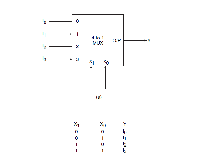
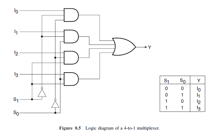
A 4:1 MUX takes the concept of data selection further by allowing four data inputs (I0, I1, I2, I3) and two control inputs (X0, X1). These two control inputs together determine which of the four data inputs is transmitted to the output.
The truth table for a 4:1 MUX is as follows:

4:1 MUXs are commonly used in data selectors, multiplexing lower-order address bits, and designing arithmetic circuits.

8:1 MUX — Expanding Possibilities
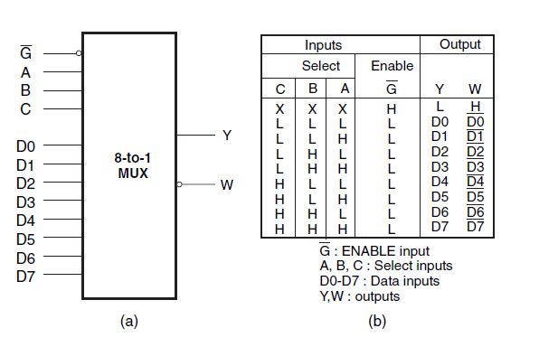
An 8:1 MUX goes a step further by providing eight data inputs (D0 to D7) and three control inputs (A, B, C). This allows for the selection of one out of the eight data inputs to be transmitted to the output.
The truth table for an 8:1 MUX is as follows:

8:1 MUXs are widely used in memory access circuits, address decoding, and complex multiplexing operations.

16:1 MUX — Embracing Complexity
The 16:1 MUX takes the idea of data selection to even greater heights, featuring sixteen data inputs (D0 to D15) and four control inputs (A, B, C, D). This MUX is designed to select one out of the sixteen data inputs to be transmitted to the output.
The truth table for a 16:1 MUX is relatively larger but follows the same logic as previous MUX configurations.

Applications of 16:1 MUXs are found in large-scale data routing, high-performance memory systems, and complex multiplexing scenarios.
Conclusion
Multiplexers, in their various configurations, form the backbone of digital circuit design. From the fundamental 2:1 MUX to the more sophisticated 16:1 MUX, each configuration serves a unique purpose in the world of data routing and selection. By understanding the principles and applications of these MUXs, engineers and enthusiasts alike can harness their potential to build efficient and powerful electronic systems that drive technological advancements across various industries.
Reference
Earl D. Gates — Introduction to Electronics
Anil K. Maini — Digital Electronics
Comments
Post a Comment